Keithley 197 Microvolt DMM

My Fluke 101 handheld multimeter makes the basic measurements, except for current. To remedy this metrology1 void, I needed to get a multimeter that can measure current. I got very lucky and found these two Keithley bench top DMMs. The EBay seller was eager to sell these two units and I managed capture both units for $60. They even came with power cords, which is a very nice surprise.

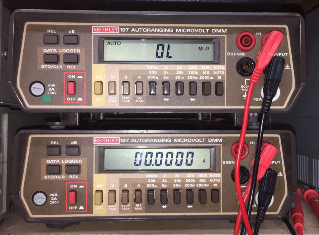
The Kethley 197 is a bench top 5 1/2 digit digital multimeter that measures AC and DC voltage, AC and DC current, resistance, and includes a diode tester.

Here are a couple links from a couple other Keithley 197 owners. A teardown and a repair.

Keithley AN-USM-486A DMM
Keithley AN-USM-486A DMMs

Honorably Discharged from the U.S. Army

The DMMs safely arrived and I noticed that they had stickers indicating that these instruments were owned by the U.S. Army. They had calibrations stickers dating to the mid-1990s. I think the EBay seller likely acquired these units from a government auction.

The front panel labels this model as a Keithley 197 Autoranging Microvolt DMM, but on the bottom of the chassis, there is a label identifying this model as a AN-USM-486A. Apparently, Keithley made special models of the their 197 DMM specially for the US military.

A Few Differences

This military version of the 197 DMM is identical to the standard Keithley 197 except for a few differences.

  • The AN-USM-486A does not have a backlight LCD display. The civilian Keithley 197 includes a backlight illuminating the LCD.
  • The AN-USM-486A has a detachable power cord. The normal 197 has a permanently mounted unremovable power cord at the rear of the unit.
  • The AN-USM-486A has additional electro-magnetic shielding and extra toroidal filters within the chassis. The normal model 197 does not have these additions.

Aside from these differences, the AN-USM-486A is the same as the normal Keithley 197 DMM. There is even a data logging feature that can store up to 100 measurements.

It Needed Some Cleaning

The two DMMs work well and they seem to have both held their calibration over the decades.

The soft buttons on the top left of the front panel were sometimes unresponsive and the LCD display would sometimes not show their digits completely. Since a layer of light brown dust coated both units, perhaps the buttons and LEDs just needed a good cleaning.

The Kethley 197 service manual is available on the internet and it provides detailed instructions to disassemble the DMM. The manual is well written and comes with full schematics.

The service manual instructions were clear and easy to follow. I took apart and gave the chassis a good cleaning with compressed air. I disassembled the front panel and cleaned the contacts of the soft buttons with some fine grit sandpaper. The LED display was also easy to disassemble and I cleaned the contacts with some isopropyl alcohol. After I put it all back together, everything worked.

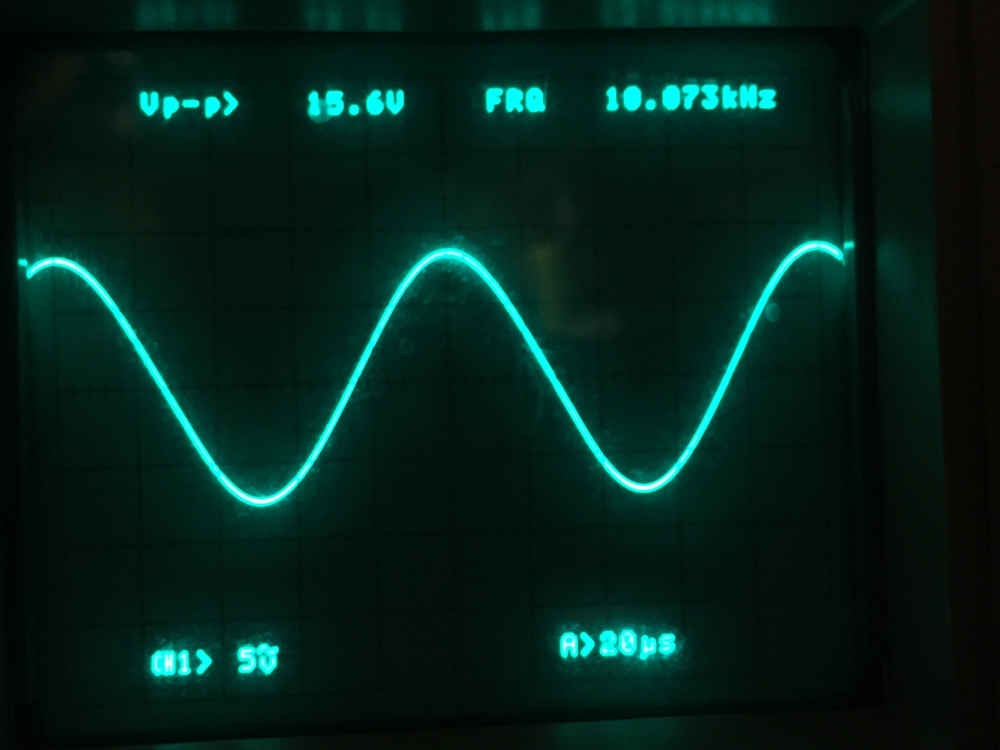
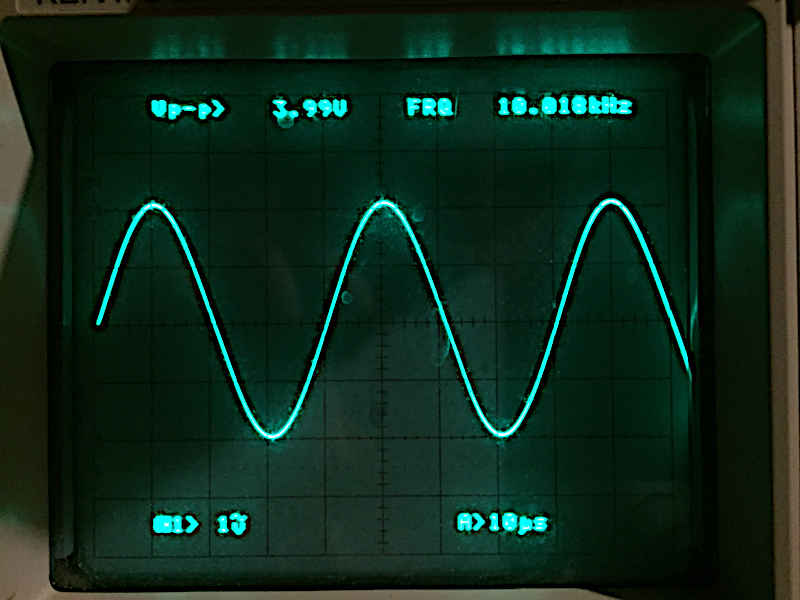
I can now measure current with the twin DMMs.

  1. Metrology is the scientific study of measurement. []

BK Precision 3011B Function Generator

My new function generator has arrived. It’s a BK Precision 3011B that I found on EBay for $20. This instrument dates to the early 1990s. 1 The previous owner was a Ham Radio Operator and he kept it in nice looking condition. The front panel is a bit worn, the background bleached and faded. But it works.

BK Precision 3011B
BK Precision 3011B

A Basic Function Generator

The 3011B is a basic function generator and it only generates waveforms as high as 2 MHz. Good for low frequency and audio projects.

There is not that much to this generator. It produces sine, square, and triangle waveforms, and it generates TTL and CMOS pulse waveforms which are useful for digital projects. The frequency readout has a large red four digit LED display.

It Works!

Here is the 3011B delivering a 10 KHz sine wave to my Kenwood Oscilloscope.

BK3011B setup
BK 3011B 10 KHz

As you can see above, the LED display is nice and bright. But the LED background is a bit too reflective, and the unlit elements of the LED are much too visible. This makes the display hard to read unless it is dark with the lights off in the lab.

The LED display has two decimal digit resolution. And, the frequency counter reads a little bit high, so it needs calibration. I’m not sure if it even can be calibrated.

The output voltage goes as high as 10V with a 50 ohm load. However, the minimum output voltage does not go all the way to zero volts. The lowest that it will go is about 1.5V. I don’t know if this is by design or by defect, and the specifications do not state a minimum output voltage value. This will be a problem if I want to do low voltage measurements. I plan to do measurements that require signal amplitudes of 0.22 volts (or 0.0 dBm at 50 ohms, which I will explain in future posts) and much much lower. Clearly, this is not the instrument to use for those measurements.

Is that Distortion I see?

Reducing the output from the generator and increasing the timebase resolution on the oscilloscope reveals greater detail on the waveform. The 3011B emits a very unclean signal. As you can see below, there is a slight defect in the waveform to the right of the maximum peak and a very jagged defect just after the minimum peak is reached. I begin to see this distortion at frequencies greater than 5 KHz and it just gets more pronounced at higher frequencies up to the 2MHz maximum. There is definitely some problem in the circuit causing this distortion.

BK3011B 10 KHz Sine Wave
BK-3011B 10 KHz distorted sine wave

A clean and pure sine wave looks like this.

Similar Distortions

A brief search engine query revealed another BK 3011B owner who has a very similar sine wave distortion on his unit. Here is his YouTube Video. 2 Although the distortions he is seeing are not exactly the same as seen on my generator, they are very similar and they are positioned in the same places on the sine wave as shown on my 3011B. Actually, his distortions look quite worse than what I am seeing on my generator. This seems to be a systemic problem that is common to the 3011B. 3

Yet, It’s Still Useful

The square wave and triangle waveforms also show the similar defect as seen in the sine wave. However, this generator is still useful for producing TTL and CMOS square waves for digital circuits.

Even though the waveform is distorted, output voltage doesn’t go very low, and the LEDs are hard to read. I can’t complain about the price and the instruction and service manual are available on the internet.

It’s good for very quick and crude measurements.

  1. The instruction manual has a copyright date of 1992. []
  2. The fellow with this similar problem tried fixing it but he could not find a solution to the problem. []
  3. In my opinion, it’s likely a problem within the BK 3011B waveform generation circuit. []

The Wien Oscillator

Now that I have my new oscilloscope and power supply, I am now ready to put together a circuit. I chose to make a simple oscillator circuit; the Wien Oscillator. 1

This circuit is an oscillator and its only job is to create a simple Sine Wave. If you’re interested, you can get the details from the many good references available on the web. Here are some examples. 2 But, I will just build the circuit and see the output on the oscilloscope.

There are many different ways to implement a Wien Oscillator. But I will be using a very simplified implementation with a minimum number components. I will use an Operational Amplifier with four resistors and two capacitors. Digging around my old junk box of electronics from college, I found a Texas Instruments ‘741 Op-Amp,3 a bunch of resistors, some ceramic capacitors, and breadboard and wires.

Op-Amp Implementation

The ‘741 op-amp is an old device dating back to the 1960s. There are many modern op-amps with better performance characteristics and more convenient to use, but people still use it today. One inconvenience of the ‘741 is that it demands two voltages from the power supply. 4 This circuit needs +18V and -18V 5 and, fortunately, my power supply has dual outputs. 6

I wanted to create a sine wave of 10 KHz, so I needed to find the right combination of resistors and capacitors that will cause the circuit to resonate at that frequency. I couldn’t find any resistors or capacitors with the necessary values. So instead, I found two capacitors that were very close in value and adjusted the needed resistances by combining several resistors together to create the required resistance values. This network of two resistors and two capacitors determines the frequency of the sine wave generated. The two other resistors in the circuit determine the amount of feedback that the ‘741 op-amp will produce. One resistor needs to be twice the value of the other. So, I used one resistor and a potentiometer for the other resistor so I can make fine adjustments to the value as needed.

Shown below is the Wien Oscillator circuit.

Wien Oscillator
Wien Oscillator

With the circuit finished, I connected the power supply and connected the oscilloscope probe to the output of the op-amp, applied power and saw…. Nothing.

Wien Oscillator Circuit

Needs Adjustment

The power supply was on and delivering +18/-18V and confirmed it with the Fluke 101 multimeter. The power was good and the circuit was connected properly. So, unless the op-amp is burned out, the only possible cause is not enough feedback to keep an oscillation running. This is where the potentiometer, or “pot”, comes into play. I adjusted the pot to modify the ratio of the two op-amp feedback resistors. I turned the pot counter-clockwise. That didn’t work. So, I turned the pot clock-wise and success! A nice sine wave appeared on the oscilloscope screen.

Here is the sine wave on the oscilloscope.

wien 10 KHz sine
Wien 10 KHz Sine Wave

Success!

The oscilloscope measures a sine wave of 15.6V peak-to-peak at a frequency of 10.073 KHz. Only 73 Hz high, less than 1%, from the target frequency is not bad at all. This is a very nice and clean sine wave. The Wien oscillator circuit is well known for its ability to produce a clean and pure sine wave with low distortion compared with other waveform generation techniques. 7

So, now I have a frequency generator. But it only generates a single waveform at a single frequency. To create something useful I would need a function generator. And that is on the way.

  1. The first product introduced by the Hewlett-Packard Company was a Wien Oscillator. Bill Hewlett had the brilliant idea to stabilize the circuit by adding a simple light bulb. And the rest is history. Modern Wien circuits use a Field-Effect Transistor to stabilize the circuit in place of the light bulb. []
  2. Texas Instruments Application Report SLOA060 – March 2001 []
  3. Texas Instruments LM741 Operational Amplifier Datasheet []
  4. You can setup the circuit to run on a single power supply, but that is even more inconvenient. []
  5. +18V/-18V is near the upper limit for supply voltage for the ‘741. []
  6. On the power supply, one output is set for +18V and the other output is wired for -18V by connecting the two outputs in series and using their common terminal as ground.. []
  7. Texas Instruments Application Note: AN-263 Sine Wave Generation Techniques []

Running Linux on the Mac

Suppose that you have a Mac or a Windows computer and you have a program that only runs on the Linux Operating System. What can you do? Well, why not run Linux on your Mac or Windows computer by using software Virtualization with a Virtual Machine? I only have a Mac but I do all my software development on Linux using virtualization.

What is Virtualization and what is a Virtual Machine?

“… virtualization is the act of creating a virtual (rather than actual) version of something.”

Wikipedia

A “Virtual Machine” (VM) is software that emulates a computer within a computer. So, a virtual machine allows you to run a different computer within your computer.

Virtualization and virtual machine computer technology dates back to the 1960s1, so it has been around for quite a while. But it hasn’t been available for practical use until the hardware became fast enough and memory plentiful enough for it to run on our computers.

There are a number of commercial and open source virtual machines available, and I prefer to use VirtualBox. With VirtualBox you can download and create a full emulated version of other operating systems on your computer. For instance, you can run Linux on a Mac, or run Linux on Windows. In my case, I run Linux on a Mac.

You can download and install VirtualBox for yourself from here.

Vagrant – The Virtual Machine (VM) Manager

Although you could very well create and run Linux on the Mac by simply using VirtualBox directly, I prefer using a virtual machine manager to create and startup the VM running on my computer. Using a VM manager package called Vagrant makes my life easier. Vagrant is a sofware package that simplifies the process of creating, starting up, and maintaining virtual machines on your system.

You can download and install Vagrant for yourself from here. Be sure to install VirtualBox, or similar VM software, first on your system because Vagrant will use the VM software to create the VMs so you don’t have to do it yourself.

At the Vagrant web site, there is a clear tutorial on how to install Ubuntu Linux in a VM on your system.

So, get VirtualBox and Vagrant installed and give it a try. In a later post I will show you how I got Arch Linux installed and running on my Mac.

  1. https://en.wikipedia.org/wiki/Virtual_machine []