Now that I have my new oscilloscope and power supply, I am now ready to put together a circuit. I chose to make a simple oscillator circuit; the Wien Oscillator. 1
This circuit is an oscillator and its only job is to create a simple Sine Wave. If you’re interested, you can get the details from the many good references available on the web. Here are some examples. 2 But, I will just build the circuit and see the output on the oscilloscope.
There are many different ways to implement a Wien Oscillator. But I will be using a very simplified implementation with a minimum number components. I will use an Operational Amplifier with four resistors and two capacitors. Digging around my old junk box of electronics from college, I found a Texas Instruments ‘741 Op-Amp,3 a bunch of resistors, some ceramic capacitors, and breadboard and wires.
Op-Amp Implementation
The ‘741 op-amp is an old device dating back to the 1960s. There are many modern op-amps with better performance characteristics and more convenient to use, but people still use it today. One inconvenience of the ‘741 is that it demands two voltages from the power supply. 4 This circuit needs +18V and -18V 5 and, fortunately, my power supply has dual outputs. 6
I wanted to create a sine wave of 10 KHz, so I needed to find the right combination of resistors and capacitors that will cause the circuit to resonate at that frequency. I couldn’t find any resistors or capacitors with the necessary values. So instead, I found two capacitors that were very close in value and adjusted the needed resistances by combining several resistors together to create the required resistance values. This network of two resistors and two capacitors determines the frequency of the sine wave generated. The two other resistors in the circuit determine the amount of feedback that the ‘741 op-amp will produce. One resistor needs to be twice the value of the other. So, I used one resistor and a potentiometer for the other resistor so I can make fine adjustments to the value as needed.
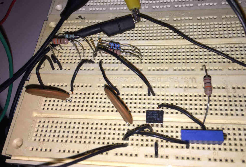
Shown below is the Wien Oscillator circuit.
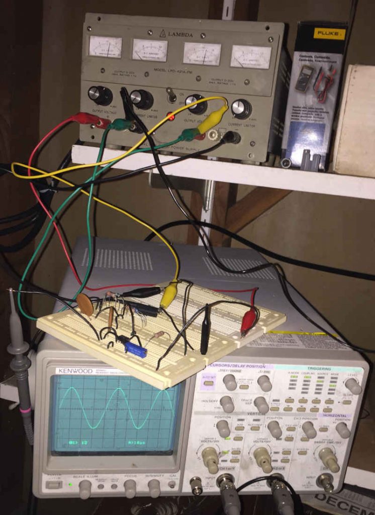
With the circuit finished, I connected the power supply and connected the oscilloscope probe to the output of the op-amp, applied power and saw…. Nothing.
Needs Adjustment
The power supply was on and delivering +18/-18V and confirmed it with the Fluke 101 multimeter. The power was good and the circuit was connected properly. So, unless the op-amp is burned out, the only possible cause is not enough feedback to keep an oscillation running. This is where the potentiometer, or “pot”, comes into play. I adjusted the pot to modify the ratio of the two op-amp feedback resistors. I turned the pot counter-clockwise. That didn’t work. So, I turned the pot clock-wise and success! A nice sine wave appeared on the oscilloscope screen.
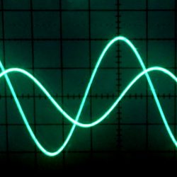
Here is the sine wave on the oscilloscope.
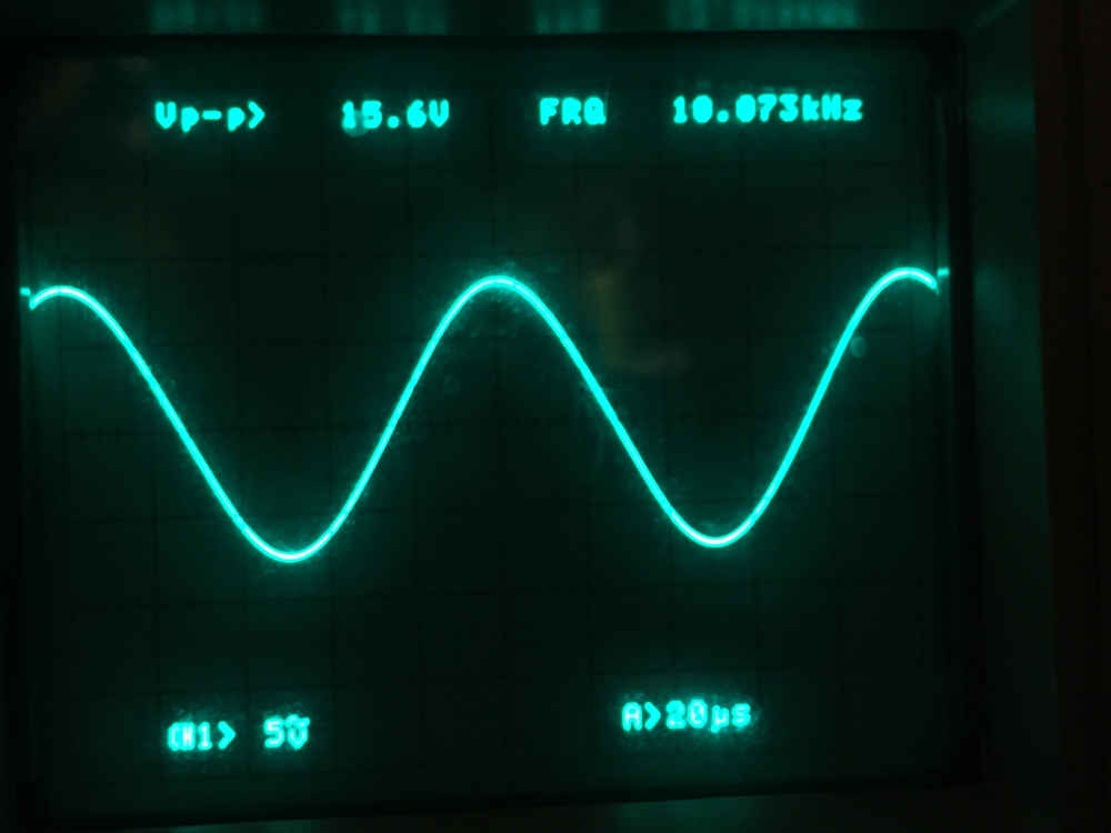
Success!
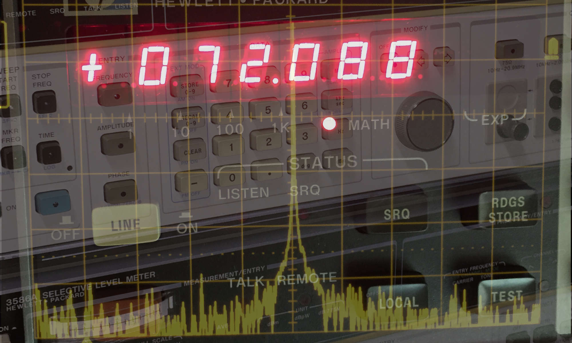
The oscilloscope measures a sine wave of 15.6V peak-to-peak at a frequency of 10.073 KHz. Only 73 Hz high, less than 1%, from the target frequency is not bad at all. This is a very nice and clean sine wave. The Wien oscillator circuit is well known for its ability to produce a clean and pure sine wave with low distortion compared with other waveform generation techniques. 7
So, now I have a frequency generator. But it only generates a single waveform at a single frequency. To create something useful I would need a function generator. And that is on the way.
- The first product introduced by the Hewlett-Packard Company was a Wien Oscillator. Bill Hewlett had the brilliant idea to stabilize the circuit by adding a simple light bulb. And the rest is history. Modern Wien circuits use a Field-Effect Transistor to stabilize the circuit in place of the light bulb. [↩]
- Texas Instruments Application Report SLOA060 – March 2001 [↩]
- Texas Instruments LM741 Operational Amplifier Datasheet [↩]
- You can setup the circuit to run on a single power supply, but that is even more inconvenient. [↩]
- +18V/-18V is near the upper limit for supply voltage for the ‘741. [↩]
- On the power supply, one output is set for +18V and the other output is wired for -18V by connecting the two outputs in series and using their common terminal as ground.. [↩]
- Texas Instruments Application Note: AN-263 Sine Wave Generation Techniques [↩]